Power Supply
This is the first installment in a series on the electrical refit of Hale Kai. At present, the electrical system is arranged as follows. There are two 110AH wet led acid batteries, one in a port-side cockpit locker, one under the cabin sole in front of the engine. The negative bus is the negative terminal on the battery under the cabin sole and this is connected to a bolt on the engine.
The batteries are connected to a heavy-duty switch that allows to select one or both batteries and connect to the main positive electrical bus. The positive bus is, effectively, the output terminal on this switch, to which is connected the engine starter motor and alternator as well as a secondary bus behind the control panel, and from there to fuses and lights, instruments and whatnot.
Perhaps it would be clearer with a diagram:
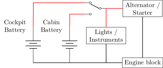
The battery in the cabin sole, with its negative terminal functioning as the bus is like this:

This setup, while basic and easy to understand, has a number of deficiencies. To begin with, there is no separation between starter battery for the engine and house bank. This means that all of the on-board electrics are permanently connected to the engine’s alternator. Not only does this mean that they must tolerate transient high-voltage spikes as the engine is started, but that they must also tolerate 14.4V continuously. This last is a problem if we want to upgrade the house bank to more efficient LiFePO4 batteries. Using the negative terminal of one of the batteries as a bus is also not ideal: what if the battery needs to be removed?
A more reasonable arrangement is shown in the following diagram:
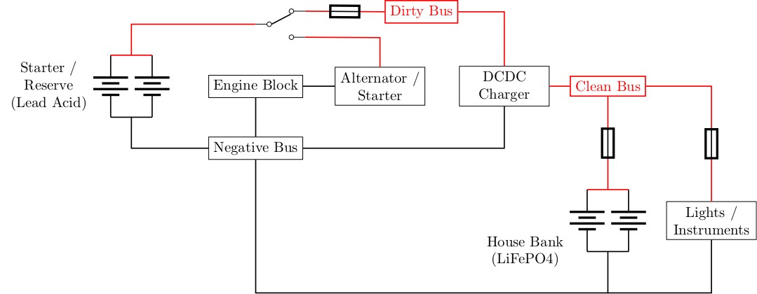
Here, the lead acid batteries (220AH) act to start the engine and double as reserve power. They can be switched to the engine, or to the “dirty bus”, or both. This enables the reserve batteries and/or the alternator to be connected to the dirty bus, as well as any other input (e.g. eventual solar or wind generation). The dirty bus is connected to a DC-DC charger that conditions the power and charges a bank of LiFePO4 batteries (200AH) to power the house and any downstream, possibly sensitive electronics. All of the fuses in the diagram are rated for 100A.
Having moved the old cabin battery to the box in the cockpit locker, the resulting house bank looks like this:
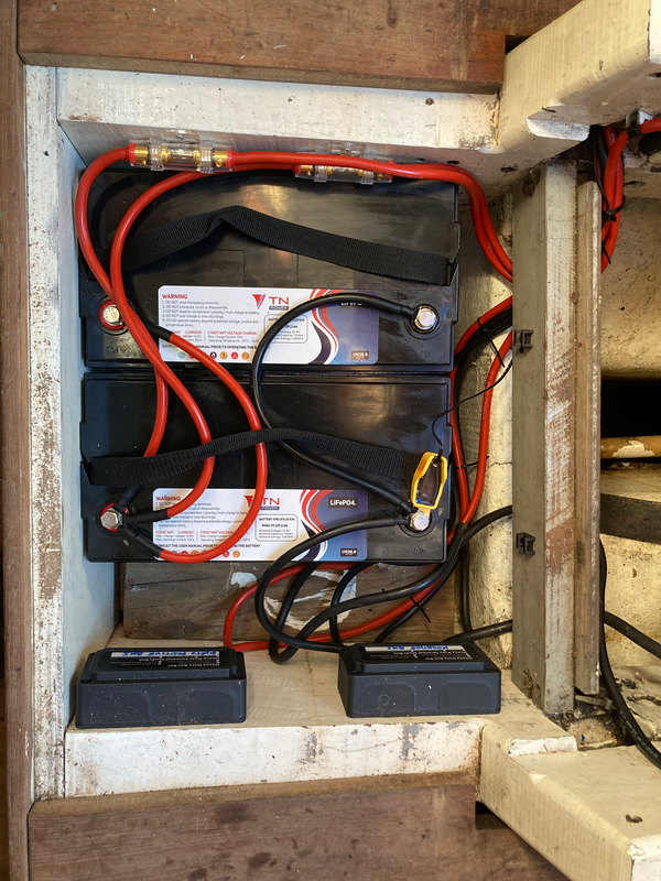
where the negative bus bar is at the bottom right, and the dirty bus at the bottom left. Not shown is the Sterling Power 60A battery to battery charger which is in the locker underneath the chart table.
This new arrangement means that the house bank can be easily charged from the alternator or other power sources that can be added later such as solar, wind or shore power. Essentially anything that is connected to the dirty bus. In extremis, the house bank can even be charged from the starter / reserve bank. When the starter / reserve bank is connected to the dirty bus, it is also charged from whatever sources are available though care must be taken that the available generation capacity exceeds the consumption otherwise the reserve bank will be drained.
It is not directly possible to start the engine from the house bank (for example if the reserve bank has become drained). In an emergency this can be done by removing the fuses connecting the house bank to the charging circuit and the lights and other instruments, and connecting them directly to the dirty bus. This configuration should not be maintained for long, however, as the alternator can quickly damage them, but it will be enough to start the engine.
The next article in this series will attack the fuse box and control panel which is in dire need of an upgrade.